


3-inch Suspension Lift Kit Installation
3-inch air suspension
lift guide
Porsche Cayenne / Volkswagen Touareg
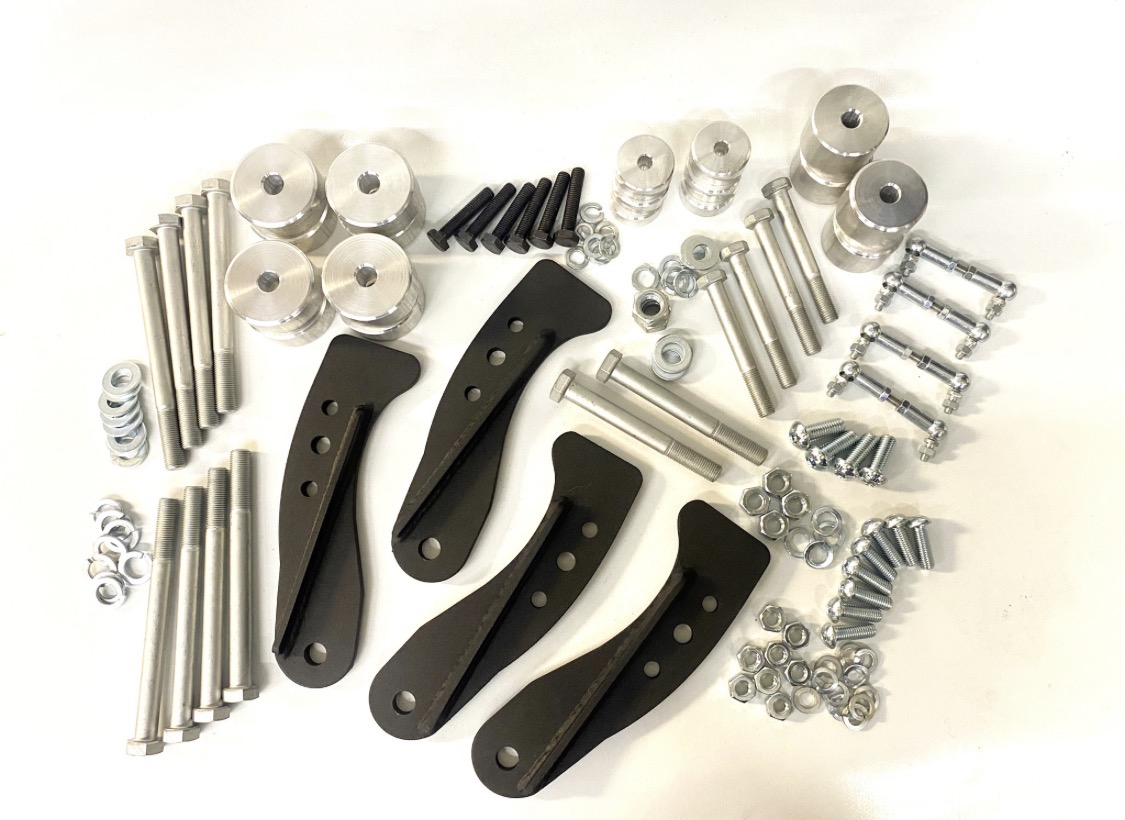
Review edition. Confirm the exact kit procedure and resolve the torque discrepancies before installation.
01 / Before you start
This is a review edition for the Cayenne / Touareg 3-inch air-suspension lift. Match the exact kit revision and vehicle specification before installation. The MBD4x4 product photo does not establish that every procedure or fastener specification in the supplied source applies to that kit.
Have the kit installed by a qualified professional. To the extent permitted by applicable law, TerraForge4x4 does not accept liability for damage caused by incorrect installation or improper use. Contact TerraForge4x4 before installation if anything is unclear. This statement does not limit rights or liabilities that cannot legally be excluded.
The supplied source contains conflicting torque figures and omits step 16. These gaps remain open; this edition is not released as a complete workshop procedure.
02 / Tools and preparation
Prepare a wiper-arm puller, a 12 mm XZN (triple-square) socket, Torx bits, large and small pry bars, spanners and sockets with extensions, and a paint marker. The supplied preparation list mentions 10, 13 and 16 mm tools; the connection list below requires additional sizes. Access above the wing may require a suitable step platform.
The source specifies normal ride height and suspension locking before lifting. Confirm the vehicle-specific suspension-disable procedure and dashboard confirmation before proceeding. Use the prescribed lifting points and rated supports on a stable surface. Do not work under a vehicle supported only by a jack.
Loosen wheel bolts before raising the vehicle; remove the wheels once safely supported. Never disconnect pressurised air-suspension components without the approved depressurisation procedure.
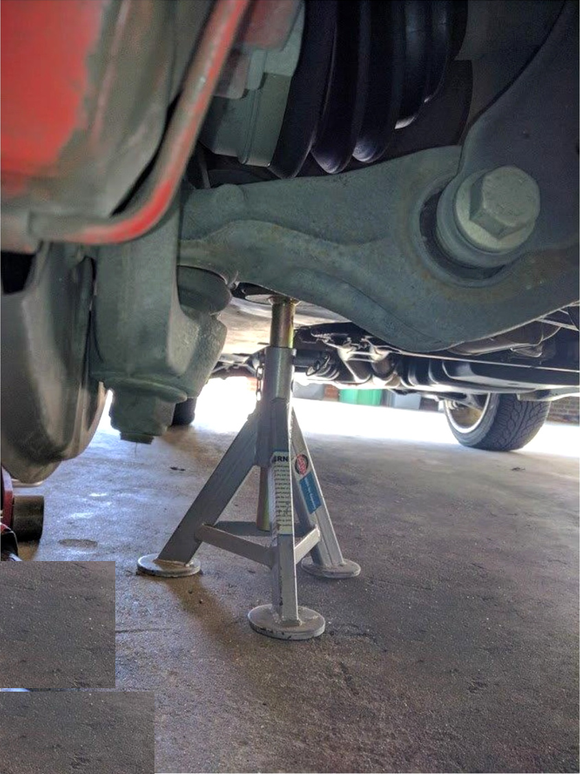
03 / Source steps 7–10: marking and initial access
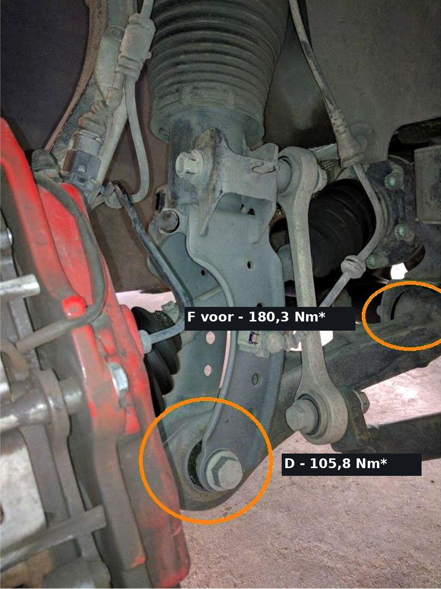
7. Mark the positions of the eccentric bolts and washers securing the lower control arms to the subframe (F). Record their position relative to the surrounding bracket. These marks assist reassembly but do not replace wheel alignment.
8. Apply penetrating oil to the relevant seized fasteners, keeping it away from braking surfaces.
9. Remove the applicable engine-bay trim covers and perimeter seal for access. The source describes quarter-turn plastic fasteners.
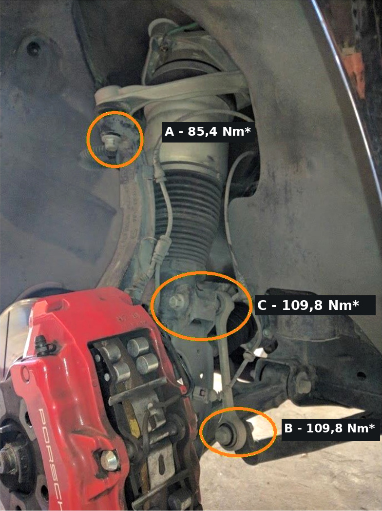
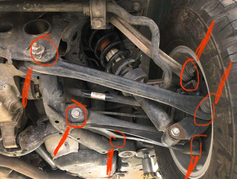
10. The source identifies the connections below for initial loosening, without complete removal. Check the actual hardware before selecting tools. At D and F, loosen from the nut side; do not force the eccentric bolt head or washer.
A: upper control-arm ball joint to knuckle — 18 mm. B: anti-roll bar to link — two 18 mm tools. C: link to air strut — two 18 mm tools. D: air strut to lower control arm — two 19 mm tools. E: lower ball joint — 21 mm. F: lower control arm to subframe — two 21 mm tools. G: track-rod end to knuckle — 21 mm; the source describes this as optional.
04 / Source steps 11–12: upper access
11. With the vehicle prepared, remove the wipers and cowl if required for access to the upper mounts.
12. Optional access work: the source describes removing the vacuum pump and engine torque strut when replacing the torque strut or brake-vacuum hose. This is not a requirement for every vehicle or lift installation.
For the vacuum pump, the source describes disconnecting the electrical connector and hose/clamp, then removing two 10 mm bolts. For the engine torque strut it specifies a 12 mm XZN socket and 15/16/17 mm socket provision at the engine-mount side. This tool-size notation has been retained following the owner's confirmation for the Cayenne; select the size matching the fitted fastener.
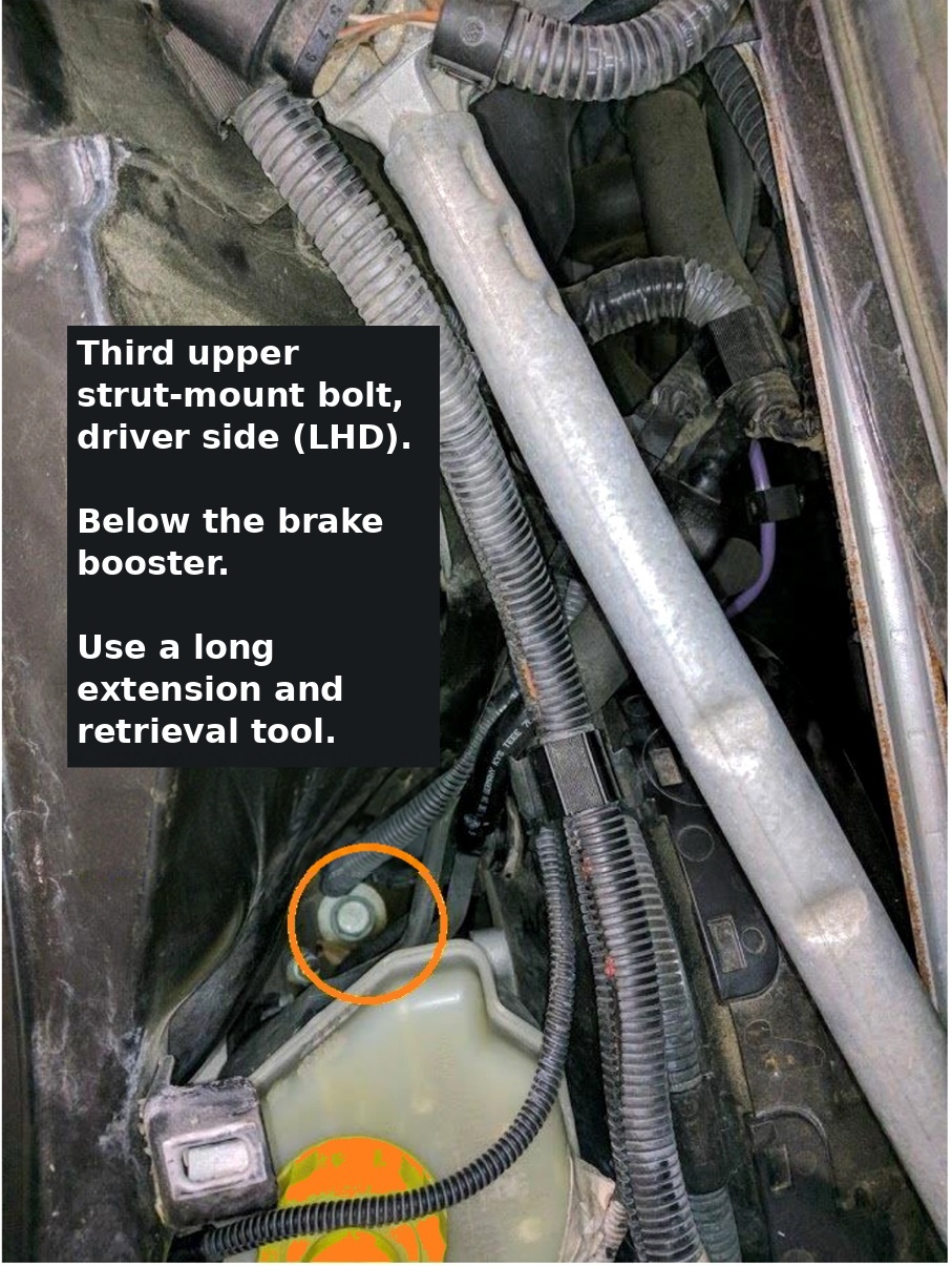
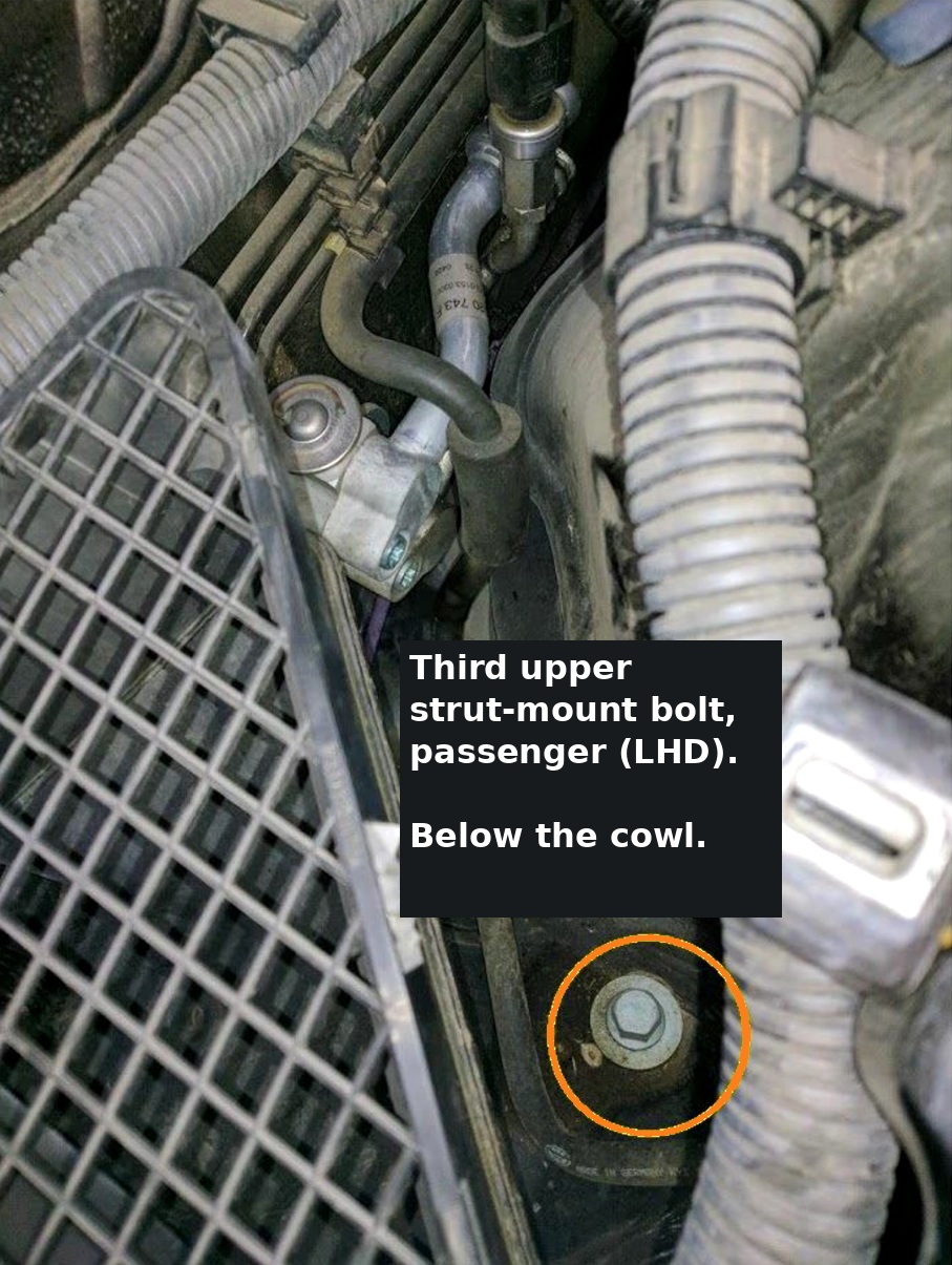
The third upper strut-mount fastener is under the cowl. Left-hand-drive and right-hand-drive descriptions vary in the source: identify the actual vehicle layout before dismantling.
05 / Source steps 13–15: mounts and connections
Locate all upper strut-mount fasteners and keep the strut supported. Record the cable and hose routing before releasing any retainers.
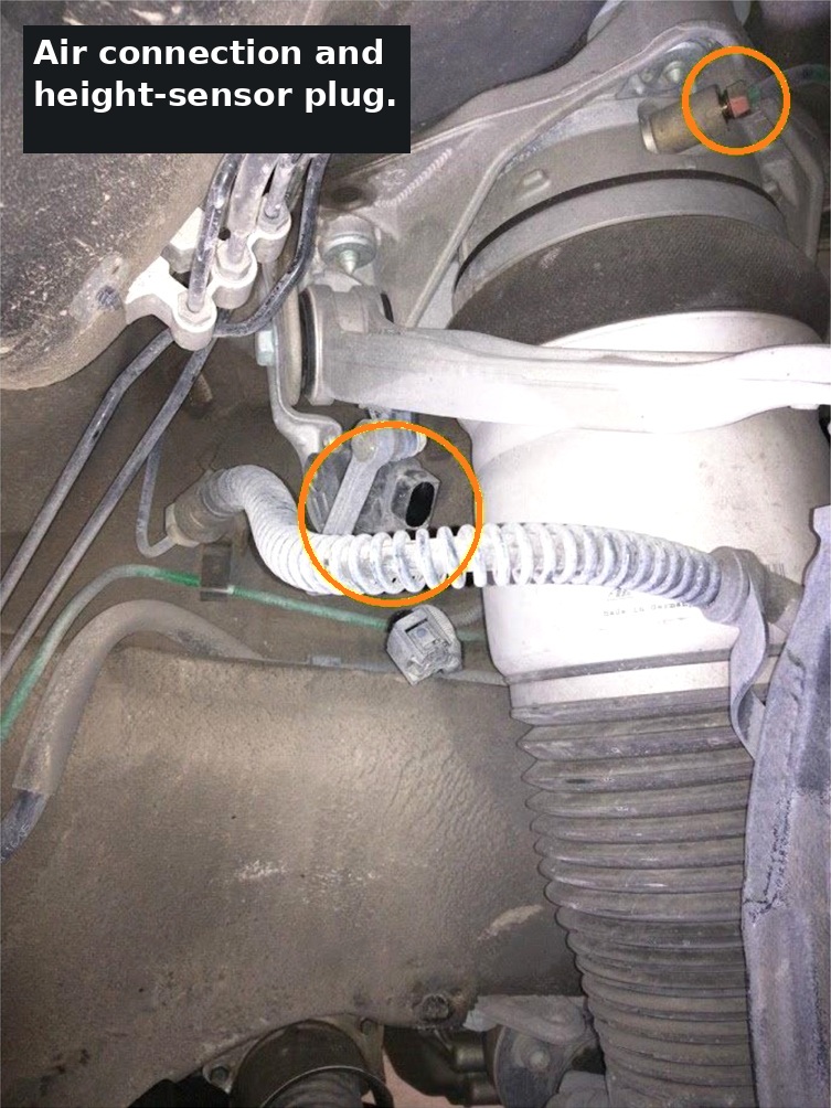
The source illustrates the small air-line connection at the top of the air strut and the ride-height sensor electrical connector. Establish the correct pressure-release method before disconnecting the air line. Do not use mounting bolts to vent residual pressure.
Step 16 is missing from the supplied sequence and has not been invented.
06 / Source steps 17–24: strut removal
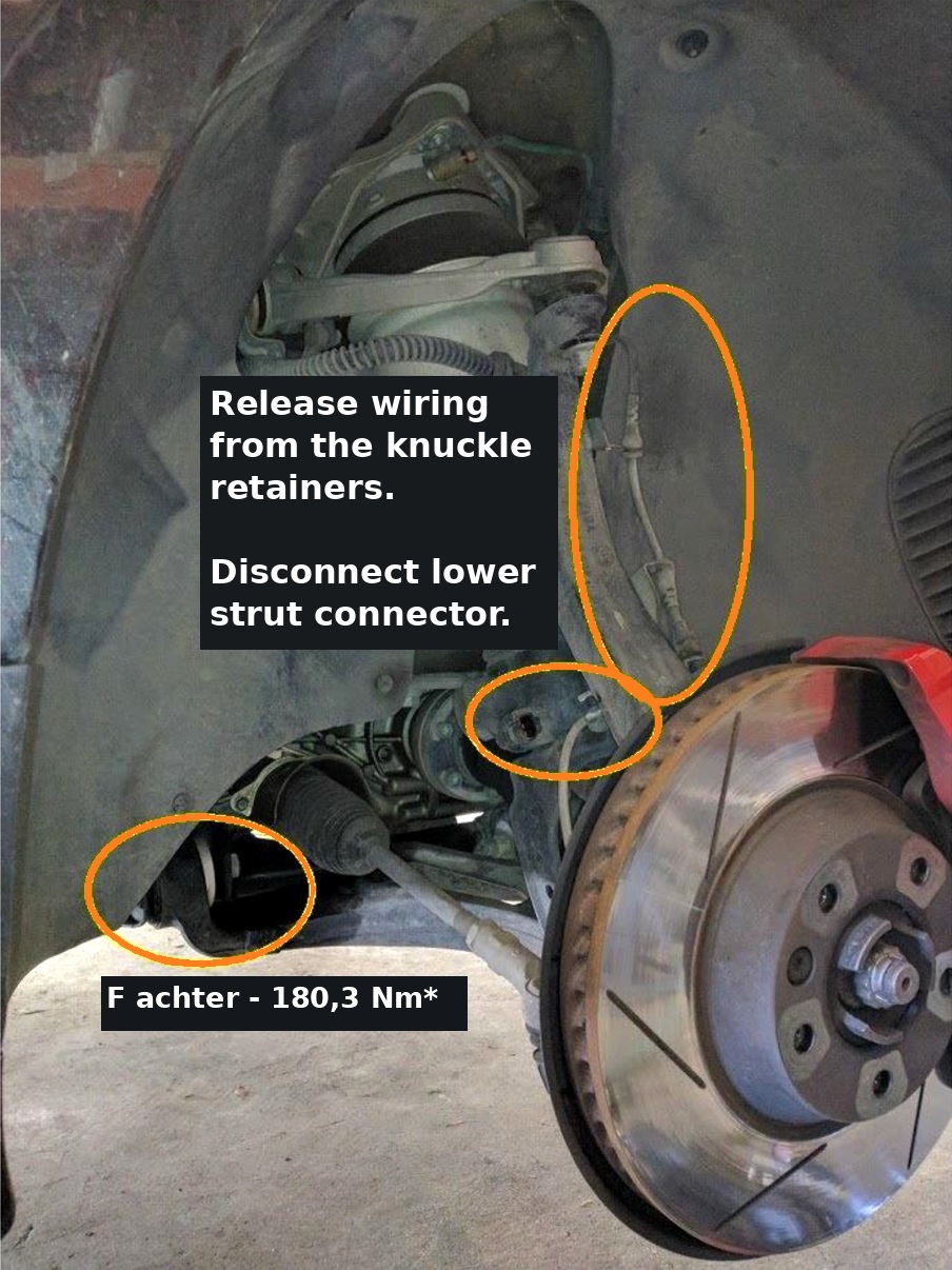
17. Release wiring from its retaining brackets and disconnect the lower strut connector as applicable. Provide sufficient slack without straining hoses or cables.
18. Disconnect the applicable anti-roll-bar link connection. Stored suspension loads must be controlled before removing fasteners.
19–20. Separate the upper ball joint using the appropriate workshop procedure and support the knuckle/hub assembly. Do not allow its weight to pull on wiring, brake hoses or the driveshaft.
21. Disconnect the air line only after the approved depressurisation procedure has been completed.
22–23. With the strut safely supported, remove the remaining upper and lower fixings and extract the strut without snagging lines.
24. The source discusses upper-mount removal and residual pressure. Its method of releasing pressure through mounting bolts is not reproduced as a validated procedure. Use the vehicle and strut manufacturer's instructions. Do not rest the strut on the driveshaft.
07 / Subframe drop and upper spacers
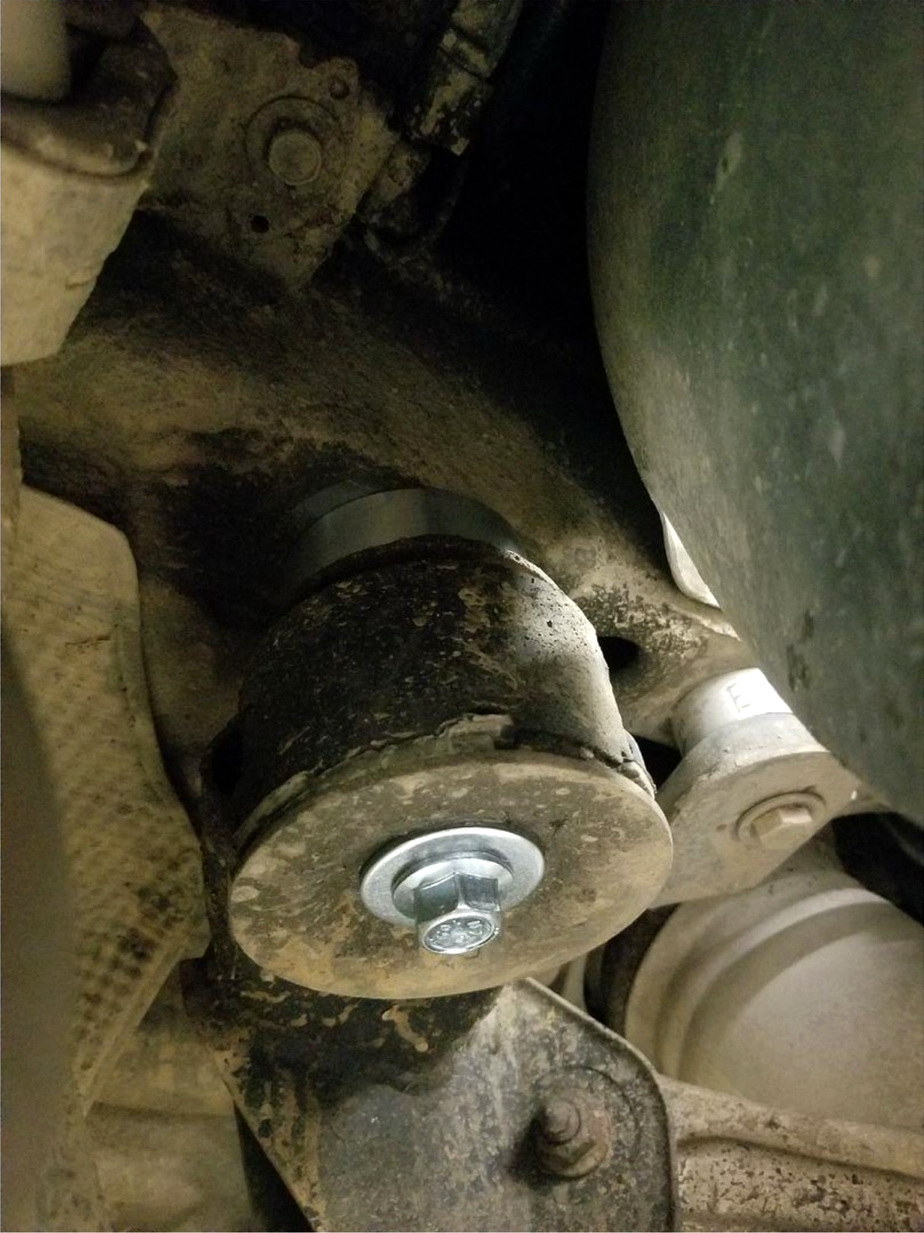
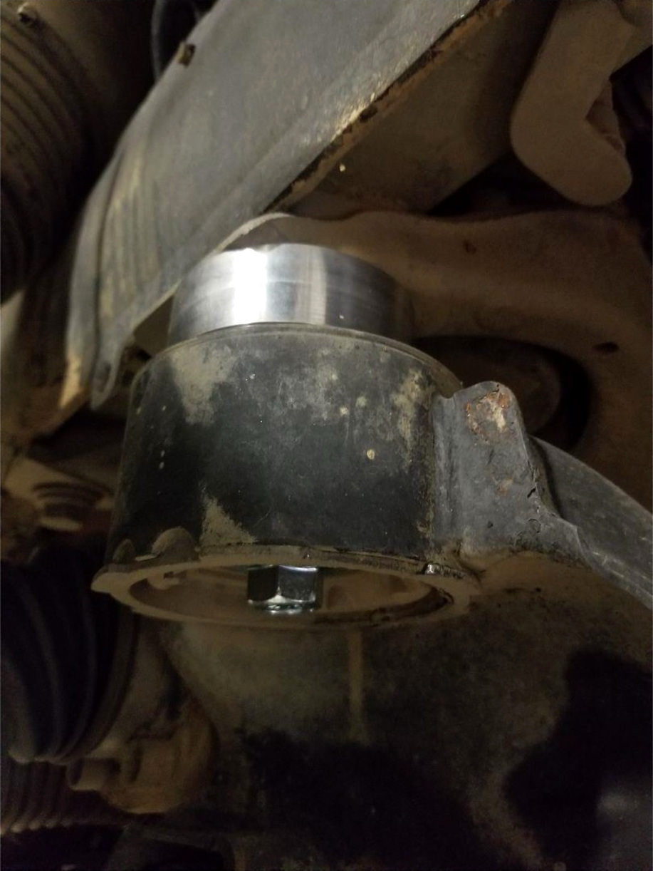
The source overview shows nominal 1-inch subframe spacers and longer hardware at eight front/rear subframe attachment points. Support the assemblies and establish the exact kit procedure before lowering them. Check steering connections, hoses, wiring and exhaust clearance throughout movement.
The source also shows six front upper-mount spacers, fitted with the supplied longer bolts. Preserve their correct orientation and seating. Do not use a generic suspension torque figure for kit-supplied replacement bolts unless the manufacturer confirms it.
08 / Front strut extensions
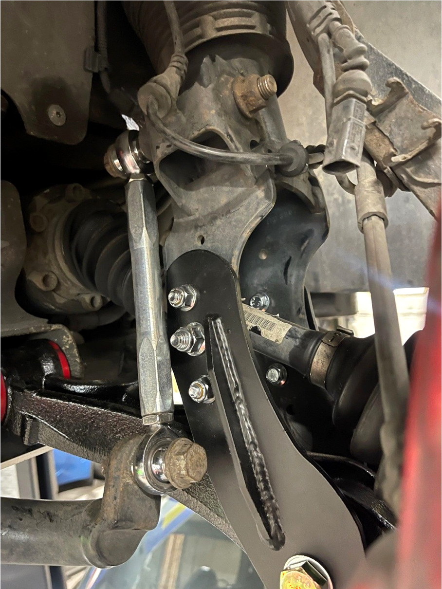
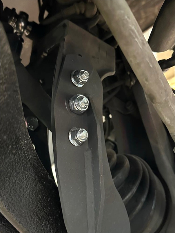
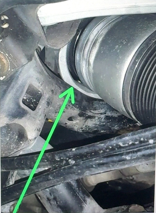
Install the correct extension brackets and supplied packing washers for the kit revision. The source shows washers taking up the space between the strut and control arm.
At the forward side of the illustrated connection, bolts must point from inside the strut outward to avoid driveshaft contact. The source's reference to the back side describes the connection, not the rear axle. Verify the drawing and physical clearance for the exact kit.
Check clearance around the shaft, air strut, cables and brake hose through the permitted suspension travel.
09 / Sensor bracket and clearance
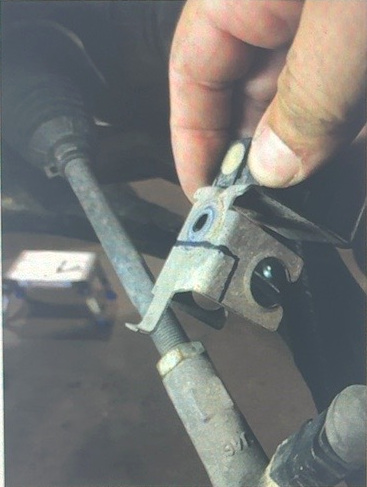
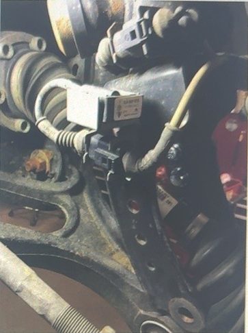
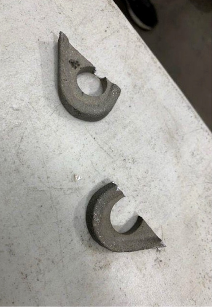
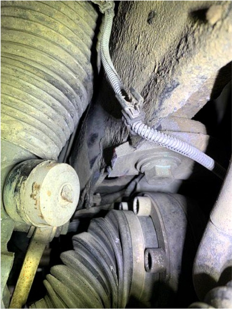
The source identifies possible contact between subframe tabs and a lower strut sensor. Some versions use a separate sensor bracket and some do not.
Bracket reshaping, tab removal and other irreversible modifications require confirmation for the exact vehicle and kit. Retain the sensor's specified orientation. These illustrations show the reported arrangement; they do not authorise cutting unidentified structural material.
10 / Rear cradle spacers
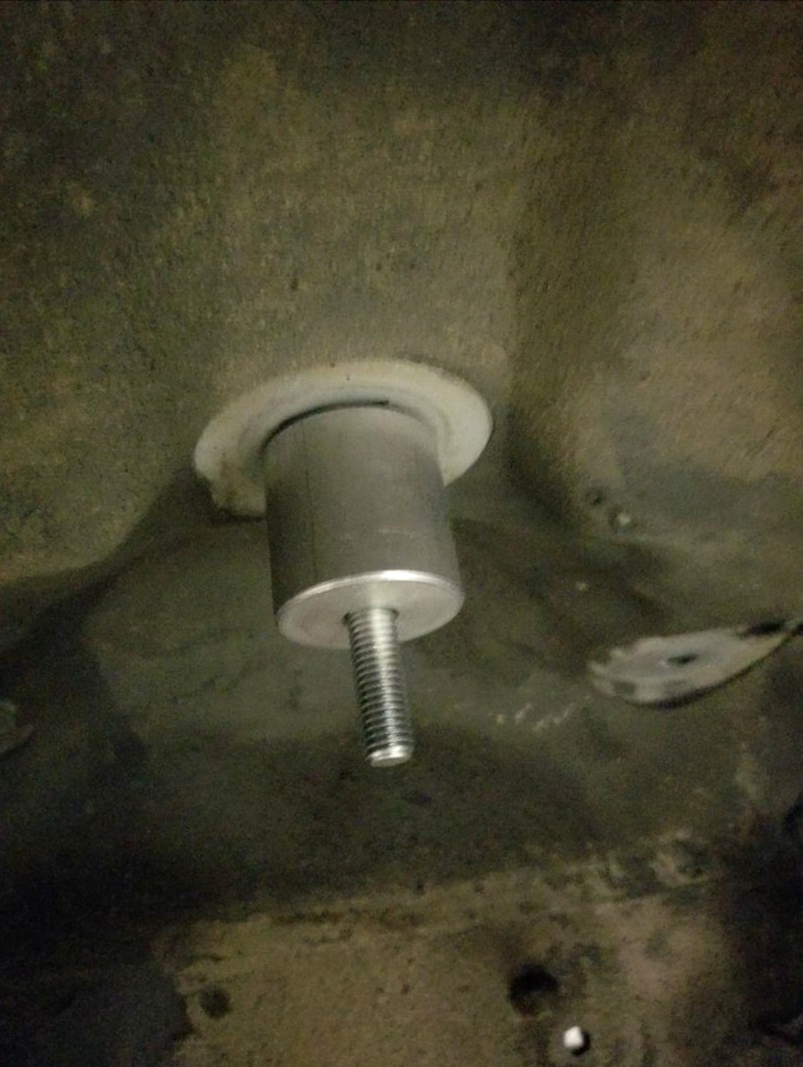
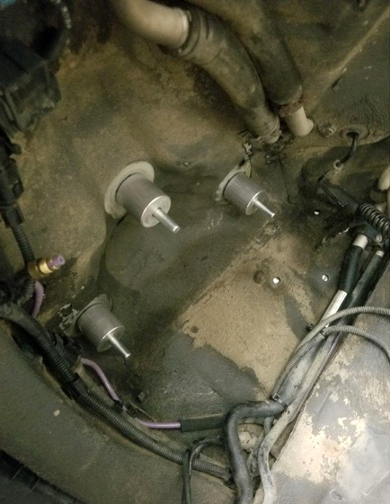
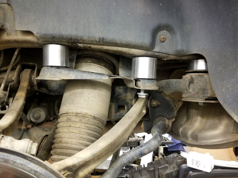
The rear spacers shown fit at the upper support cradle. The source describes four fixing bolts and replacement longer hardware. It also refers to 2-inch rear spacers within the nominal 3-inch kit; individual spacer thicknesses must not simply be added to calculate wheel lift.
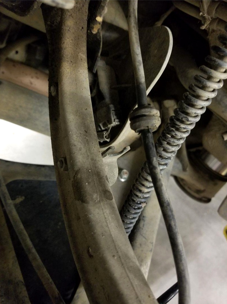
Support the cradle and control its movement. Confirm whether the illustrated brake-line operation means releasing a retaining clip or opening a hydraulic connection before proceeding. Avoid loading hoses or wiring.
Check spacer seating and all clearances after reassembly. Use the approved support and fitting method for the kit.
11 / Exhaust lowering
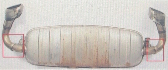
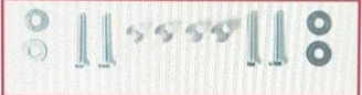
Use the specified rear silencer lowering spacers and hardware where required by the subframe-drop package. The source shows separate hardware for this operation.
After lowering, the tailpipes may need repositioning in the rear bumper openings by adjusting the relevant clamps. Confirm clearance and secure the exhaust with the specified torque values.
12 / Control-arm bushes and ride height
Rubber-bushed pivots must be tightened in the specified loaded/ride-height position to avoid unwanted preload. Follow the vehicle procedure and fastener replacement requirements. The pivot illustration includes coil springs and is used only to identify the general pivot areas.
The source describes adjustable sensor links and states that lengthening lowers the vehicle while shortening raises it. Confirm this behaviour for the actual linkage arrangement before adjustment.
The source recommends normal/Auto height and warns about increased driveshaft angles in higher modes. Establish the permitted modes for the exact kit and vehicle before use.
13 / Torque conversion and unresolved conflicts
All torque values below are in Nm. Extra tightening angles remain separate. Conversion alone does not validate a torque specification.
A: original photo 63 lb-ft = 85.4 Nm; later table 95 Nm — unresolved conflict.
B and C: original photos 81 lb-ft = 109.8 Nm; no matching confirmation in the later table.
D: original photo 78 lb-ft = 105.8 Nm; later table 150 Nm + 90° — unresolved conflict.
F: original photo 133 lb-ft = 180.3 Nm; later front control-arm table 180 Nm. Confirm joint identity before use.
The source's 40–50 lb-ft reference concerns operation of a ball-joint separator (54.2–67.8 Nm), not a vehicle-fastener tightening specification.
14 / Front torque reference — supplied source
| Connection | Fastener | Source torque |
|---|---|---|
| Lower control arm / subframe | M14 × 1.5 | 180 Nm |
| Air strut / lower control arm | M14 × 1.5 × 102 | 150 Nm + 90° |
| Upper control arm / mount | M10 | 50 Nm + 90° |
| Upper control-arm ball joint | M12 × 1.5 | 95 Nm |
| Strut top mount / body | Not specified | 50 Nm + 90° |
| Lower ball joint | M14 × 1.5 | 105 Nm |
| Track-rod end | M14 × 1.5 | 90 Nm |
Source reference only. Confirm against the vehicle and kit specifications.
15 / Rear torque reference — supplied source
| Connection | Fastener | Source torque |
|---|---|---|
| Crossmember | M12 × 1.5 × 80 | 90 Nm + 90° |
| Lower control arm / subframe, forward | M14 × 1.5 | 150 Nm + 90° |
| Lower control arm / subframe, rearward | M14 × 1.5 | 180 Nm |
| Toe link / subframe | M14 × 1.5 | 180 Nm |
| Toe link / spindle | M16 × 1.5 | 150 Nm + 90° |
| Upper arm / subframe, forward | M12 × 1.5 | 90 Nm + 90° |
| Upper arm / subframe, rearward | M12 × 1.5 | 90 Nm + 90° |
| Upper arm / spindle, forward | M14 × 1.5 | 150 Nm + 90° |
| Upper arm / spindle, rearward | M16 × 1.5 | 150 Nm + 90° |
Source reference only. Confirm against the vehicle and kit specifications.
16 / Troubleshooting and final checks
If knocking occurs at the rear, inspect for worn or loose mounts and evidence of contact near the upper air-strut mount. Do not remove material without an approved repair procedure. Preserve contact marks for diagnosis.
Before release: resolve torque conflicts; confirm kit and vehicle compatibility; verify fastener replacement and tightening requirements; check loaded bush positions, hose routing, electrical connections and air leaks; establish permitted height modes; check tyre and exhaust clearance; complete a four-wheel alignment and controlled road test; record the inspection and follow-up checks.
Gen1 -3 inch Lift Kit (Air Suspension)
Compatible with Porsche Cayenne 955 and 957, Volkswagen Touareg 7L, and Audi Q7(4L) with air suspension.
Installation Steps
- Vehicle Preparation.
- Front Suspension Installation.
- Rear Suspension Installation.
- Height Sensor Adjustment.
- Final Checks.
- Torque Specifications.
Torque Specifications
Use manufacturer torque specs for all subframe, control arm, and spacer bolts.