PL71 Suspension Lift Geometry Guide
TerraForge4x4 technical guide
PL71 Suspension Lift Geometry Guide
Porsche Cayenne 955/957 · Volkswagen Touareg 7L · Audi Q7 4L
This guide explains the suspension and driveline checks that become important when lifting first-generation PL71-family vehicles.
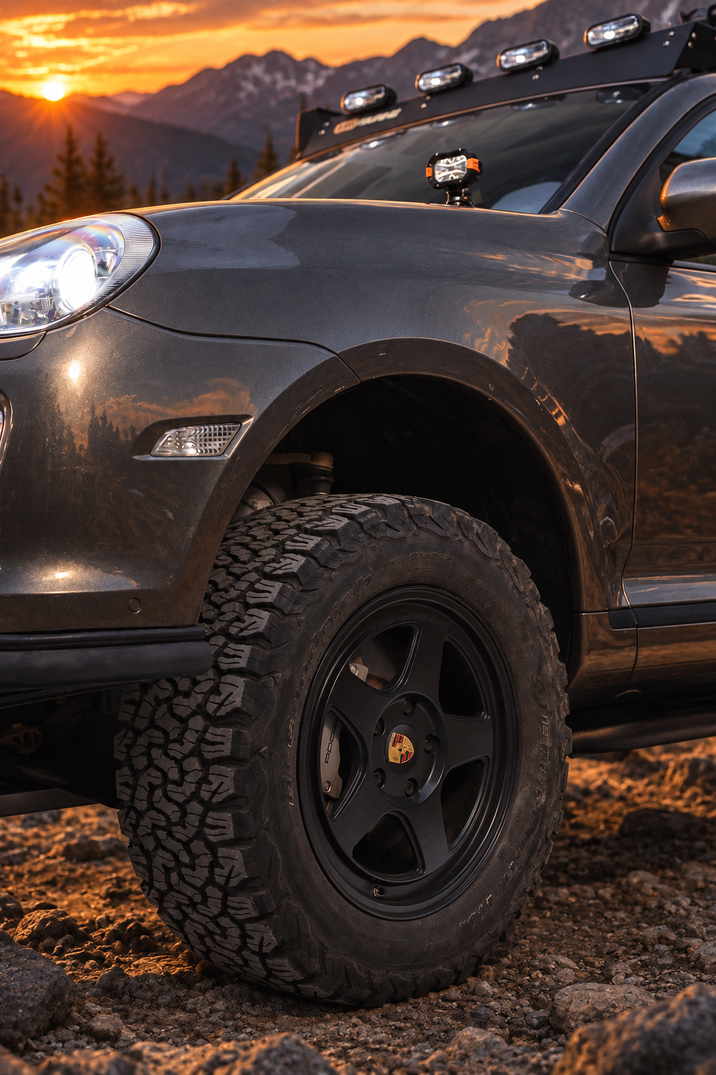
Planning guide: this is not a universal parts list or replacement for the vehicle workshop manual. The correct solution depends on model, suspension type, lift method, measured ride height and vehicle condition.
01 / Vehicles covered
The first-generation Porsche Cayenne, Volkswagen Touareg and Audi Q7 were developed from the same Volkswagen Group SUV architecture. They share important design principles, but this does not mean that every suspension part is interchangeable. Engine, axle, brake, spring, air-suspension and model-year differences can change fitment. Use only parts that explicitly list your vehicle.
| Vehicle | Generation and years | Important note |
|---|---|---|
| Porsche Cayenne | 955 and 957 · 2002–2010 | Do not assume compatibility with Cayenne 958. |
| Volkswagen Touareg | 7L · 2002–2010 | Touareg 7P uses different components. |
| Audi Q7 | 4L · 2005–2015 | Confirm Q7 fitment for every individual part. |
Parts for a PL71 lift
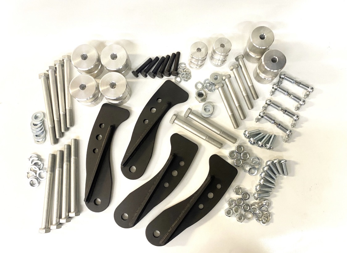
The exact combination depends on the vehicle, suspension type and measured lift height. Do not order solely by the advertised lift size. Confirm fitment for the Porsche Cayenne 955/957, Volkswagen Touareg 7L or Audi Q7 4L before installation.
| Part | When it may be required | What to verify |
|---|---|---|
| Vehicle-specific lift kit | The basis of the build: coil-suspension spacers, air-suspension spacers or a complete matched kit. | Exact model, model year, air or coil suspension, front and rear components, supplied bolts and installation instructions. |
| Subframe or drivetrain drop kit | Commonly considered with larger lifts to reduce CV and driveline angles. | Compatibility with the lift kit, number and position of spacers, steering shaft, hoses, wiring, exhaust and hardware length. |
| Corrected upper control arms | May be needed when standard alignment adjustment or ball-joint articulation is insufficient. | Camber and caster correction, joint travel, three-bolt ball-joint fitment, wheel clearance and load rating. |
| Adjustable anti-roll bar links | Used when the original links preload the anti-roll bar at the final ride height. | Required length measured at normal operating height, joint angle and clearance through full travel. |
| Air-suspension height-sensor links | For some air-suspension lift methods, alone or together with electronic calibration. | Correct orientation and adjustment range; verify sensor readings and all available height modes. |
| Extended or repositioned brackets | Where brake hoses, sensor cables or other lines lose safe travel after lifting. | No tension, rubbing, kinking or contact at full steering lock, compression and droop. |
| Replacement mounting hardware | For kit-supplied brackets and any vehicle fasteners specified as single-use. | Correct grade, diameter, thread, length, washers, locking method and manufacturer torque procedure. |
| Alignment and calibration | Required after the complete lift and correction package is installed. | Four-wheel camber, caster and toe; steering-centre and air-suspension calibration where applicable. |
Important: a 2-inch or 3-inch lift is a complete setup, not just one spacer. Inspect the finished geometry and add correction parts based on measurements and the kit manufacturer’s instructions.
02 / What changes when the vehicle is lifted
A lift changes the normal working position of suspension arms, joints, anti-roll bars, height sensors and driveshafts. The amount of change is determined by the actual increase in hub-to-fender height, not only by the advertised size of the kit.
Upper control arms and ball joints
As ride height increases, the upper arms and ball joints operate at a different resting angle. Available droop and joint articulation can be reduced. Check for binding through the full steering and suspension range, inspect the boots and confirm that the joint retains adequate movement.
Anti-roll bar links
Fixed-length links may hold the anti-roll bar away from its neutral position after a lift. This can increase preload and reduce independent wheel movement. Adjustable links can be set with the vehicle resting at its final ride height, but their required length must be measured rather than guessed.
Air-suspension height references
Vehicles with air suspension use mechanical level sensors and electronic calibration. Depending on the lift method, correction may involve sensor-link adjustment, electronic calibration or both. Incorrect settings can cause implausible height readings, limited level selection or repeated height corrections.
Driveshaft and CV-joint angles
Raising the chassis relative to the wheel hubs can increase the resting angle of the front driveshafts and CV joints. Inspect boots, joints and shafts before fitting a lift. A subframe or drivetrain drop may reduce angle on some configurations, but it must be matched to the lift kit and vehicle.
Camber, caster and toe
Lifting changes the position of the control arms and can move camber, caster and toe away from their original values. Measure alignment after all lift and correction components are installed.
03 / Symptoms to investigate
| Symptom | Possible causes to check |
|---|---|
| Clunk over bumps | Anti-roll bar preload, worn links, ball joints, bushes or loose hardware. |
| Vehicle changes height or reports level faults | Sensor-link geometry, calibration, wiring, stored faults or air-system leakage. |
| Uneven tyre wear or unstable steering | Camber, caster, toe, worn joints, bushes or tyre pressure. |
| Reduced front-axle articulation | Anti-roll bar preload, joint travel or damper travel. |
| Vibration under acceleration | CV angle, worn joints, shafts, mounts or wheel-and-tyre condition. |
| Damaged CV boots | Excess joint angle, boot age, contact or installation damage. |
04 / Planning by measured lift height
The table below is a starting point for inspection. It is not a substitute for the lift-kit instructions, measured alignment data or a physical clearance and articulation check.
Measure the actual result.
Measure vertically from the wheel-hub centre to the fender edge on level ground. Record the same vehicle load and tyre pressure before and after modification.
| Measured increase | Recommended checks |
|---|---|
| Up to about 38 mm / 1.5 in | Full alignment; verify hose, sensor-link, CV and ball-joint travel; recalibrate air suspension if required. |
| About 50 mm / 2 in | All previous checks; assess anti-roll bar preload and link length; inspect available joint and damper travel. |
| 50–75 mm / 2–3 in | Detailed geometry and driveline assessment; determine whether corrected arms and a compatible subframe or drivetrain drop are required. |
| 75 mm / 3 in and above | Treat as a complete suspension system; verify arms, joints, steering, brake hoses, sensors, CV angles, bump stops, dampers and alignment range. |
Tire fitment reference
Use this table as a planning reference for Porsche Cayenne, Volkswagen Touareg and Audi Q7 PL71-family builds. Green rows generally need little work, amber rows require trimming or fabrication, and red indicates major modification.
| Tyre size | Fitment / modification guidance | Recommended lift | Intercooler relocation |
|---|---|---|---|
| 265/65 R17 | Little to no rubbing | Stock–2.5 in | No |
| 255/65 R17 | Little to no rubbing | Stock–2.5 in | No |
| 255/55 R18 | Normally no trimming | Stock–2 in | No |
| 265/60 R18 | Normally no trimming | Stock–2 in | No |
| 265/65 R18 | Minor rubbing possible; reshape inner plastic if required | Stock–2.5 in | No |
| 265/70 R18 + 25 mm spacers | Little to no rubbing with OEM wheels | Stock | Yes* |
| 275/60 R18 · OEM suspension/wheels | Normally no trimming | Stock | No |
| 275/65 R18 | May rub at front and rear of front wheel arch | Stock–2.5 in | No |
| 255/60 R19 · OEM suspension/wheels | Normally no trimming | Stock | No |
| 255/55 R19 | Minor rubbing possible; reshape inner plastic if required | Stock–2.5 in | No |
| 275/55 R19 · OEM suspension/wheels | No trimming reported on 955/957; verify on 958 | Stock | No |
| 285/60 R18 · 955/957 only | Minor rubbing; Turbo may need intercooler relocation | 2.5 in+ | Yes* |
| 265/50 R20 | Little to no rubbing | Stock–2.5 in | No |
| 255/70 R17 | Moderate trimming may be required | 2–2.5 in | No |
| 255/75 R17 | Moderate trimming may be required | Stock | No |
| 265/70 R18 | Moderate trimming may be required | 2.5 in+ | Yes* |
| 275/70 R18 | Extensive trimming required | 2.5 in+ | Yes* |
| 285/60 R18 | Extensive trimming; Cayenne rocker-panel work may be needed | 3 in+ | Yes* |
| 285/65 R18 | Extensive trimming and rocker-panel modification | 3 in+ | Yes* |
| 285/70 R18 | Extensive trimming and rocker-panel modification | 3 in+ | Yes* |
| 33×12.50 R18 | Extensive trimming and rocker-panel modification | 3 in+ | Yes* |
| 33×10.50–33×12.50 | Extensive trimming and rocker-panel modification | 3 in+ | Yes* |
| 275/55 R20 | Trimming required | 2–3 in | Yes* |
| 33×12.50 R20 | Extensive trimming and rocker-panel modification | 3 in+ | Yes* |
| 285/50 R20 | Extensive trimming required | 3 in+ | Yes* |
| 34–35 in+ | Major trimming, fabrication and rear rocker-panel work | 3 in++ | Yes* |
Important: actual tyre dimensions vary by manufacturer. Wheel width, offset and spacers affect clearance. Always check full steering lock, suspension compression, brake-line clearance and alignment. *On 955/957 Turbo models, driver-side intercooler coolant pipes may require relocation when using larger tyres.
05 / Recommended installation sequence
- Inspect suspension, steering, driveshafts, boots, wheel bearings and tyres before modifying the vehicle.
- Install the lift according to the component manufacturer’s instructions and set the final operating ride height.
- With the vehicle safely supported, check steering lock, suspension compression and droop for binding or contact.
- For air suspension, verify sensor-link geometry and complete the required electronic calibration or basic settings.
- Set adjustable anti-roll bar links with the vehicle resting at its normal operating height and the bar neutral.
- Install any vehicle-specific geometry or subframe corrections required by measurement and the lift-kit instructions.
- Complete a four-wheel alignment and record the final camber, caster and toe values.
- Road-test at low speed, recheck fasteners after the specified settling period and inspect tyre wear regularly.
06 / Selecting compatible parts
Do not choose a correction part only because the vehicle belongs to the PL71 family. Check the exact model, model year, suspension type, engine or axle limitations and intended lift range on the product page. When a product page does not explicitly state compatibility, ask before ordering.
Browse current products: TerraForge4x4 shop
Fitment questions: info@terraforge4x4.com
07 / Frequently asked questions
Does every 2-inch lift need corrected control arms and a subframe drop?
No universal answer applies. Measure alignment range, joint travel and CV angles on the finished vehicle. Follow the lift-kit manufacturer’s instructions and use the inspection points in this guide.
Can Cayenne, Touareg and Q7 parts be mixed?
Only when the product specifically lists the relevant model. Shared architecture does not guarantee identical dimensions, load ratings or mounting details.
Do air-suspended vehicles always need adjustable sensor links?
Not always. The required method depends on how the lift is achieved and how the control system is calibrated. Some setups use electronic calibration; others use revised links or a combination.
Can this work be completed at home?
Some link and spacer work may be suitable for an experienced home mechanic. Control arms, subframe work and alignment require safe lifting equipment, correct support points, calibrated torque tools and suitable alignment equipment.
08 / Safety and legal notice
Suspension and subframe work affects steering, braking, wheel alignment and vehicle stability. Use the vehicle workshop manual and the component manufacturer’s instructions for procedures and torque values. Have the finished installation inspected and aligned by a competent workshop. The owner and installer are responsible for confirming local road-approval, inspection and insurance requirements.